Click on the pictures for a larger view.
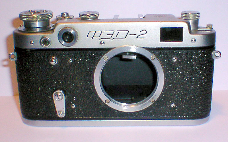
Fig 1- Fed-2
There are three screws to remove across the top. Middle screw is shorter, it covers the horizontal rf infinity adjustment. If you have one, remove the self-timer lever and the spacer underneath. Remove the decorative ring around the rf window. Remove the small lens assembly that is revealed when the decorative ring is removed, it may be hard to remove. Only use the outer two slots, the inner slots are for the vertical adjusting of the rf spot.
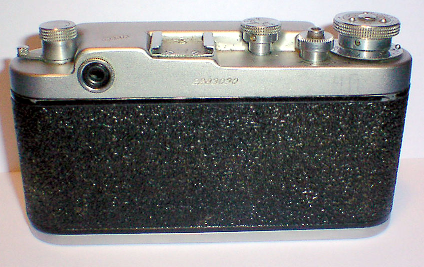
Fig 2 Fed 2 Back
To remove the rewind knob, fig 5, pull it up and remove the screw in the collar, remove the knob, collar and the fork. Set the speed knob to 'B' and loosen the two set screws to remove it. Rewind release: loosen the set screw and unscrew it from the shutter release. Advance knob, wind the advance knob to the shutter is ready to fire, loosen the set screw, unscrew the knob, the parts are shown in fig 3. Remove the cold shoe. There is one screw holding the top underneath the advance knob. Remove the viewfinder eye piece. You can now remove the top. Lift up on the right side, the diopter lever is holding the right side on, so slide the top off to the left.
Fig 3 - Advance knob
a-Advance Knob b-spring washers c-film counter d-two large thin washers e-spacer f-two small thin washers
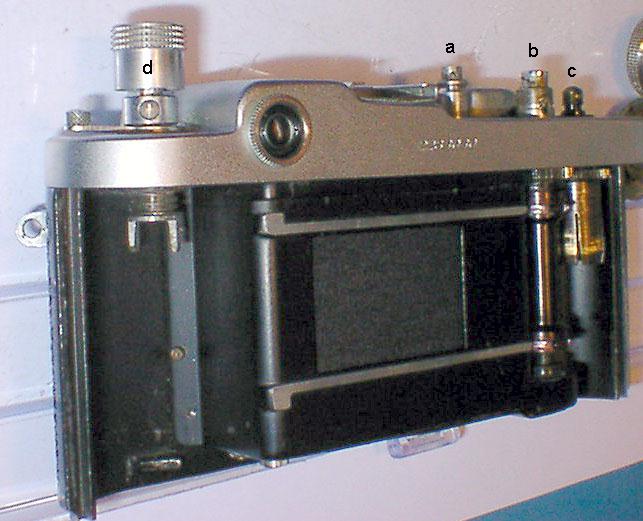
Fig 4
Rear view with some of the knobs removed
a-speed selector b-shutter button/rewind release c-film advance d-film rewind
Fig 5
The film rewind knob assembly

Fig 6
a-rf adjusting cover screw b-front of top screws c-top screw under the advance knob
On the right is the cold shoe with it's screws
Fig 7
The top of the Fed 2, rear view
Fig 8
Inside the top of the Fed-2, shutter has been fired. If the shutter is working, now would be a good time to work the advance and shutter to see how it all works. Just screw the advance knob back on to be able to do it. Watch what the tangs and the pawl do at the speed selector. The speed selector lever is attached to the first curtain, the tang underneath is the second curtain. The first curtain to be the first one to move when the shutter is fired.
a-diopter adjuster b-speed selector c-pawl d-flash contact assembly e-shutter release/rewind release
f-film advance knob mount g-screws holding shutter crate h-screws holding top shutter shield
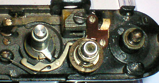
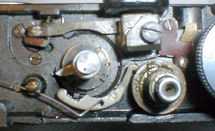
Fig 10
Close ups of the speed selector area, right one is a better view of the flash contacts
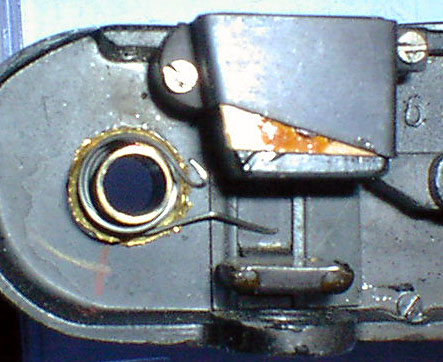
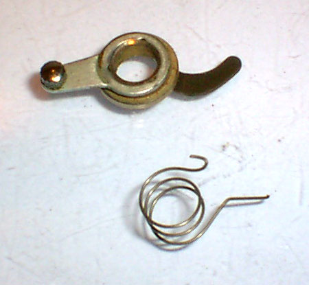
Fig 11
Diopter adjuster spring, the hook goes onto the lever, the long end pushes the lens to the back of the camera
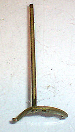
Fig 12
The shutter pawl, it holds the second curtain from releasing until the speed lever hits it or the shutter button is released.

Fig 13 Shutter speed assembly. Put a small rod or screwdriver into the hole and unscrew the cap.
Fig 14 Speed lever parts, don't loose that spring!
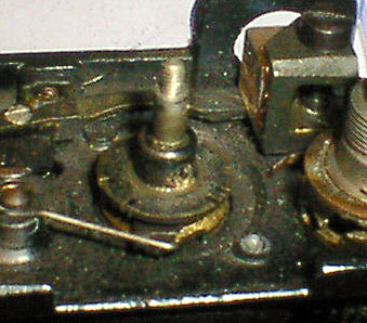
Fig 15
Exposure disc, it has the notches for the shutter speeds. Remove the screw, and pull up on the disc. It may be tight.

Fig 16 Exposure disc and mounting screw
Fig 17 n/a
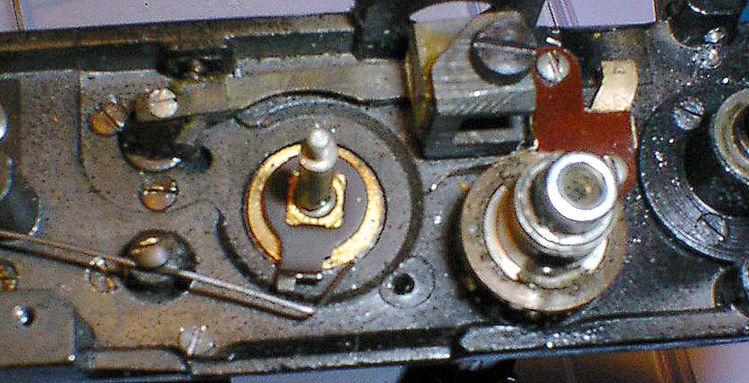
Fig 18 View with speed lever, pawl and exposure disc removed
Fig 19 A full top view
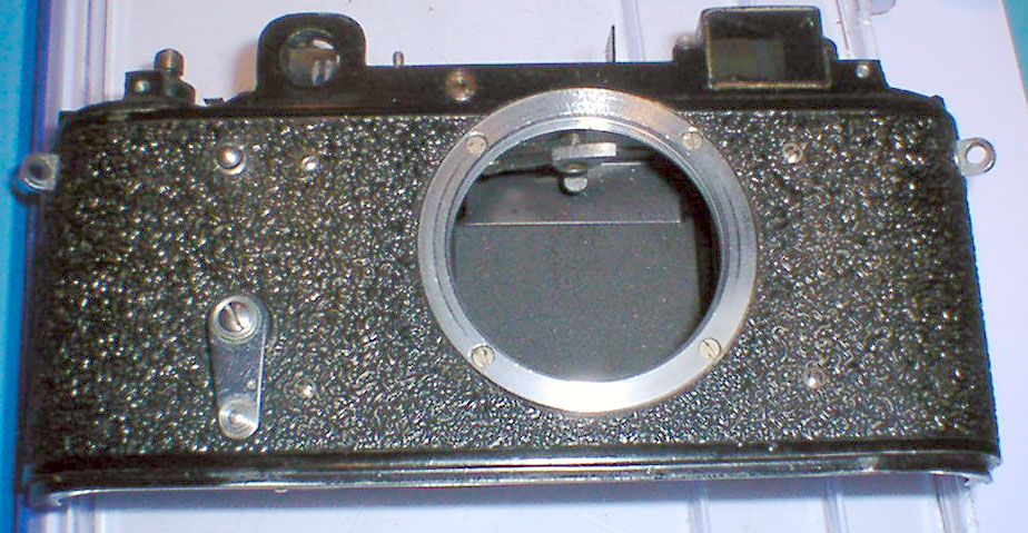
Fig 20 Front without the top, the lens mount does not need to be removed. Remove the self-timer lever, if you haven't. Remove the four chrome screws in the vulcanite.
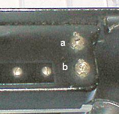
Fig 21 Tension adjustments: a-second curtain b-first curtain
Remove the little screws holding the funny nuts. Remove the two screws holding the shutter button spring, slide it over to unhook from the shutter release gear. The funny nuts are best removed after the shutter crate is removed, these are LEFT-hand threads. To remove, use a screwdriver in the slots, rotate the screw counter-clockwise to loosen, and then remove the nuts.
Fig 22 Lower shutter shield position. The small piece with the screws also hold the shutter button spring. Use a small screw driver to help line up the holes.
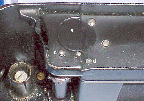
Fig 23 Bottom of shutter crate
a-restrictive gear cover b-self-timer pin c-shutter release d-pawl
Turn camera right side up and catch the self-timer pin. Remove the cover for the restrictor gear, but don't remove the gear.
Fig 24a The self-timer pin
Fig 24b Shutter release spring and it's screws

Fig 24c Lower shutter shield and it's holder
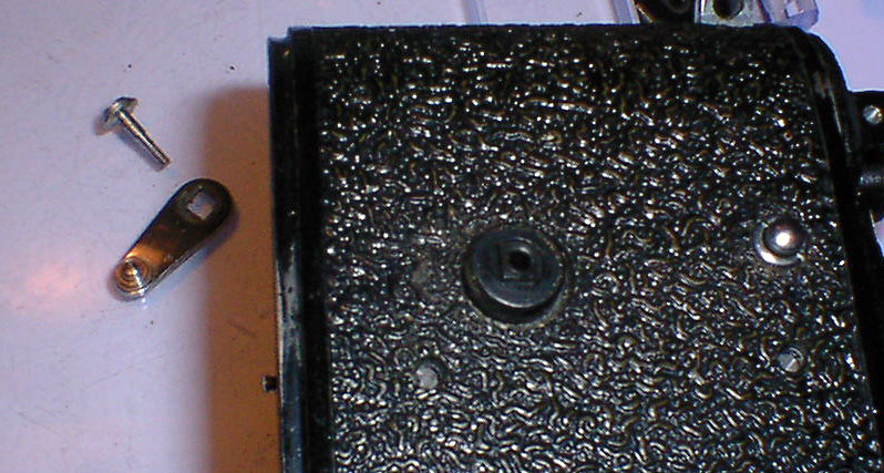
Fig 25 Self-timer with lever removed
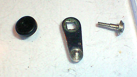
Fig 26 Self-timer lever, screw and spacer-adapter
Fig 27 The camera body with the shutter crate removed
To remove the crate, see fig 8, remove the two screws (g) points to. Position the camera as above, lift the bottom slightly and slide it out of the body. Watch for the gear in fig 28, it may come out with the assembly.
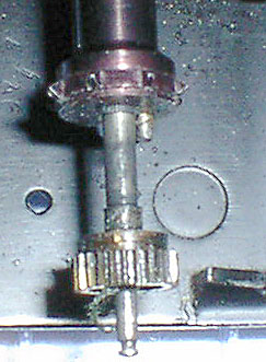
Fig 28 The shutter release and cocking gear. This must move freely and yes that is lint hanging off of it.
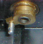
Fig 28b Shutter coupling pin, the underside of the speed selector.
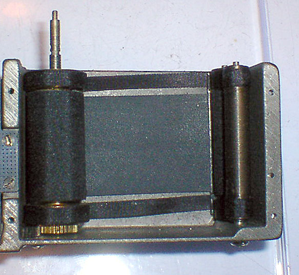
Fig 29 Shutter curtains in crate, front view

Fig 30 Shutter curtains in crate, top view
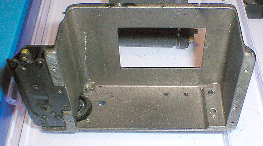
Fig 31 Shutter crate, the gear on the bottom left is the restrictor gear. The dark assembly on the left is the self-timer gear box. Don't take this apart, it's not at all easy to get back together.

Fig 32 Shutter curtain assembly, the curtains and the tapes are glued on.
a-drum b-first curtain c-second curtain
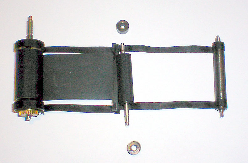
Fig 33 Shutter curtain assembly showing the rollers for the second curtain
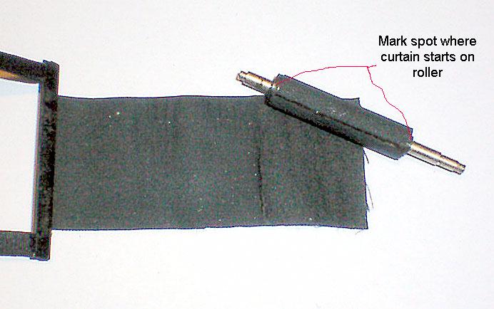
Fig 34 First curtain removed from the tension roller. Just peel it off. Also, mark the starting point of the material on the roller.
Fig 35 Close up of the lath of the first curtain
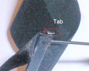
Fig 36 Opening the lath to remove the curtain. The tabs on each end need to be pried up to be able to spread open the lath
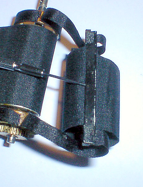
Fig 37 Using a small screwdriver to spread open the lath to remove the curtain. The curtain is glued into the lath. Be careful not to damage the other curtain or the shutter tapes, or stab yourself with the screwdriver.
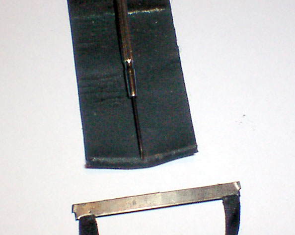
Fig 38 Curtain removed from the lath.
Fig 39 The tension roller all nice and clean. I used some carb cleaner to remove the old glue and rubber. After it's dry, put some shutter oil on the ends and work it in. Note: One of the caps on the end is threaded, make sure it tightened down. After I cleaned it, I found it had loosened up.
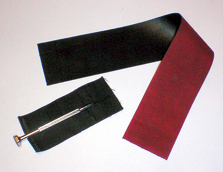
Fig 40 The old curtain and the new curtain material. Cut the new piece the same size as the old one. The screwdriver is just holding the old one flat.
Fig 41 n/a
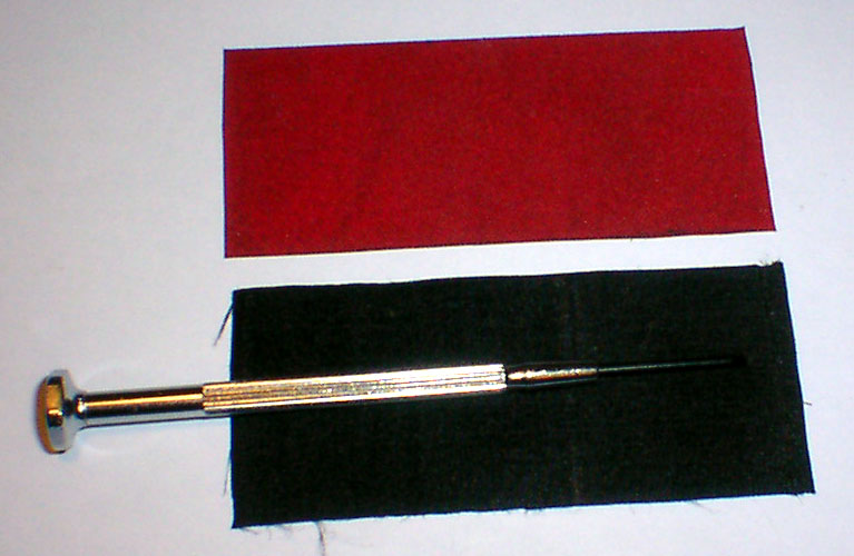
Fig 42 New shutter curtain all cut and trimmed for installation.
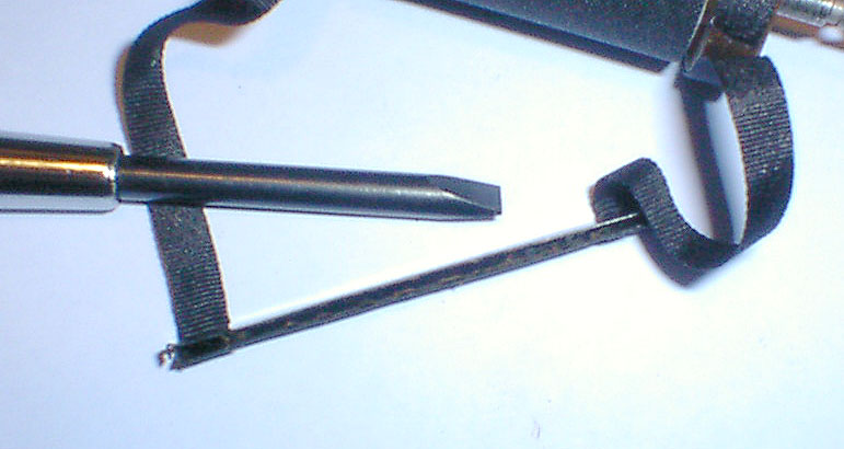
Fig 43 Spread open the lath enough so that you can put in the new one, with a screwdriver and clean out the old glue. Be careful, it bends very easily.
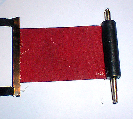
Fig 44 All glued up and ready to be reinstalled. Use some glue in the lath, insert the curtain, centered and straight, with no wrinkles. Using pliers, carefully squeeze the lath, locking in the curtain. Wait for the glue to dry. On the roller, cover it with glue and roll the curtain onto it, starting at the marks you made earlier. Make sure the notched end is at the bottom. I used a generic all purpose adhesive for the glue, another glue to use is Pliobond.
Fig 45 Curtain assembly before gluing on the roller.

Fig 46 Top of the roller
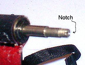
Fig 47 Bottom of the roller. The notch is to let you adjust the tension, the threads hold the funny nut.
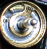
Fig 48 Top of shutter drum
a-notch in first curtain drum b-first curtain drum
The pin you see goes into (a) Fig 48 shows the notch on the correct side of (b)
If you get it wrong, you can't wind both curtains. Don't worry, it'll take a few tries putting in the shutter crate to get everything lined up and timed correctly. Also, you have to line up the restrictor gear to let the shutter to wind and release. This gear has limits the travel of the shutter. If it is off by 180 degrees, the shutter will not wind or release.
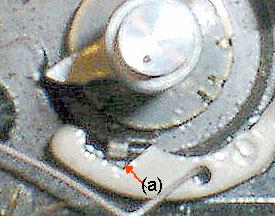
Fig 49
The tang at (a) needs to be in this position to allow proper shutter operation. Adjustment of the restrictor gear a tooth at a time will move this into the correct position. Cock the shutter, reach inside, hold both parts of the drum, remove the screw holding the restrictor gear, move it one tooth in the direction needed, and reassemble. If you put in the gear wrong, nothing can move. Wind and fire the shutter to see how it all moves.
Fig 50
a-first curtain tension adjust, b is for the second curtain, c is the restrictor gear cover, d-is the shutter release spring
Fig 51 Self-timer side view
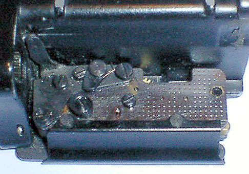
Fig 52
Self-timer rear view. The assembly at the right pushes on a pin, which pushes the shutter release spring and fires the shutter.
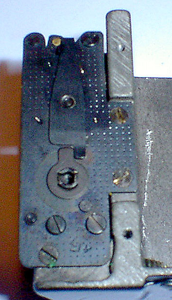
Fig 53 Self-timer top.
If your self-timer winds down before firing position, just wind the part the lever mounts on another 180 degrees. Make sure the tabbed washer is in the position shown, to be able to shove that long flat lever over to stop the timer.
Fig 54
A view of the gears, the weighted bar on the right is the part that makes the buzzing noise. It all works like a watch mechanism.